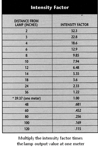
Chart 1
Until recently, calculating the necessary dosage of Ultraviolet Germicidal Energy (UV-C) in order to maintain or restore HVAC/R cooling coils to “like-new” performance depended upon trial-and-error methods and rules of thumb. This is no longer the case. The 2015 ASHRAE Handbook, HVAC Applications[i] provides specific guidance for HVAC engineers and installers hoping to incorporate UV-C fixtures to maximize heat exchange efficiency.
This article summarizes the ASHRAE UV-C dosing guidance recommendations, and provides a method to simplify future designs.
While ultraviolet germicidal energy (UV-C) offers numerous benefits for HVAC systems, it’s important to note that coil irradiation with UV-C will not, in and of itself, save energy. Rather, it’s the ability of UV-C to restore and maintain cooling coil performance, returning coil pressure drop and heat transfer efficiency to original operating conditions. This is what has the potential for saving energy of between 10 and 25%.
Benefits of a clean cooling coil
A reduction in coil performance can also encourage system controls, and often building engineers, to compensate for the loss by speeding up fans, lowering chilled water temperatures and even pumping more chilled water—regardless of metering valve positions—but all at the expense of additional energy use.
 When a coil is restored to original operating performance, many of these “adjustments” designed to compensate for inefficient airflow and poor heat transfer levels may be reversed. For example, building engineers could slow fans, add variable frequency drives (VFDs), and configure chillers back to original design parameters. Some studies demonstrate how building engineers were able to remove standby chillers from active operation and to harvest other potential energy savings through more modern control strategies. In the majority of those documented cases however, UV-C energy provided sizable energy savings, which led the ASHRAE UV-C technical committee (TC 2.9) to document this emerging technology starting in 2008.
In fact, the ASHRAE UV-C committee established minimum irradiance levels for cooling coils to: 1) eliminate mold and bacteria, 2) reduce and/or eliminate coil cleaning, and 3) sustain coil performance. Further, it states that use of UV-C can increase airflow and heat-transfer coefficient, while reducing both fan and refrigeration system energy use. Savings of 10 to 25% have been reported once capacity is restored.
Ensuring effective irradiation levels
Specifying UV-C energy can be likened to lighting a small room; where the distribution of light is paramount. For a conference room, lighting engineers use an industry reference for a specific number of lumens per square foot (amount of light) striking the conference table, for example. A common lamp for such a room is a linear 4-foot fluorescent tube. Given that, the lighting engineer can use the 4-foot fixtures “lumens per watt” baseline and size the number of fixtures, in watts, accordingly. Similarly, ASHRAE provides a recommendation in UV-C terminology; in this case it’s microwatts per square centimeter striking a coil surface as follows: “50-100 µW/cm2” (microwatts per square centimeter). The relevance of lamp watts is incorporated later.

ASHRAE’s microwatts per square centimeter amounts are based on vast amounts of application data that demonstrate that UV-C doses are cumulative. For example, the number of seconds in a 30 day month is (60x60x24x30) = 2,592,000 or nearly 2.6 million seconds. Meaning that, even one microwatt will deliver nearly 2.6 million microwatt seconds of cumulative UV-C energy, in one month. Also, the coil cleaning effect of UV-C energy will accelerate over time; as cleaner coil surfaces increase the reflectivity of the UV-C waveform making it more efficient within the coil’s fin’s interior regions. Understanding this progression is essential to appreciate how the UV-C wavelength degrades organic material buildup on a cooling coil, to restore it to near-new over time.
Using ASHRAE’s irradiation recommendations, practitioners can make use of properly marked UV-C lamps and available published lamp data to determine the minimum number of lamps required to capture the energy saving and system performance benefits of UV-C energy.
Converting microwatts per square centimeter to lamp watts
UV-C lamp manufacturers publish “microwatts per lamp watt” (µW/W) to aid in the application of their products, just like their fluorescent lamp counterparts. The UV-C data is measured and presented at one meter length from the lamp. In a plenum however, the lamps are typically installed at a distance of 12-inches from the coil surface. Both light sources (lamps) follow the same intensity principle over distance, which is known as the Inverse Square Law (I=1/d²). More simply, the closer a lamp is to a surface the more energy there is striking it.
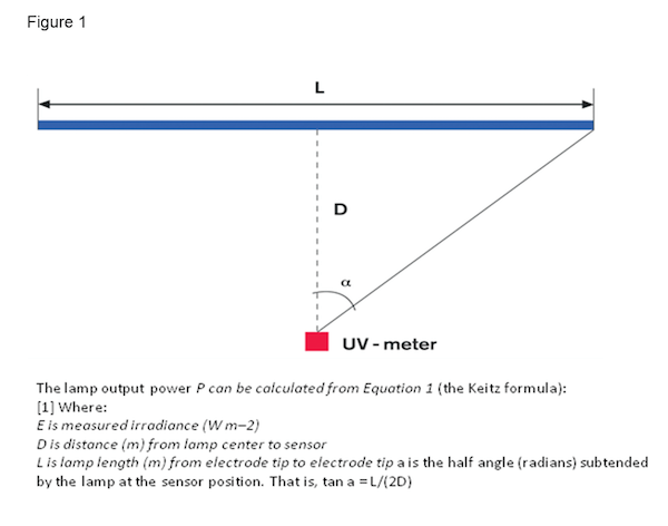
UV-C and Fluorescent lamps are diffuse area sources and not a source point (i.e., flashlight), so intensity and view factors have been developed to better represent the energy received from the source (lamp) by a surface (coil). Based on work done by Keitz (1971 – Figure 1), the factors shown in Chart 1 have been used successfully to calculate the required microwatts of energy. The chart and “view factor” (Figure 2) modeling enables designers to convert lamp manufacturers’ Watt and/or microwatt output data to a dose received at various distances, in order to arrive at microwatt values of linear lamps at 12-inches, etc.
The average 36-inch high-output (HO) UV-C lamp is rated at 80 Watts and yields 245 microwatts per square centimeter (µW/cm2) of UV-C light wave energy, at one meter, based on radiometric readings.
Using the intensity factor chart (Chart 1) we find that at 12-inches the intensity would be (245 x 6.48) = 1588 µW/cm2.
Using a more conservative cylindrical view factor model (Kowalski et al. 2000 – Figure 2), a surface would see 1375 µW/cm2 from the same lamp. Results from both approaches exceed the ASHRAE Handbook’s recommendation.
When calculating UV-C dose or energy yield, specifying engineers should take into account factors that will depreciate lamp output, and therefore impact irradiation levels, including, temperature, air velocity and reflectance.
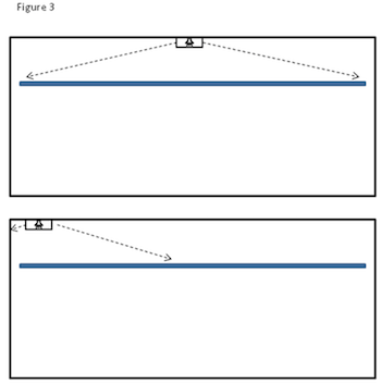 Because the most common and efficient lamps are linear, the highest amount of energy will strike the centermost part of the surface (coil) directly across from the middle of the lamp (Figure 2). Note that the lowest amount of their energy is found at either end of the lamp (Figure 2). When a single lamp is positioned at the coil, the irradiance that the “coil surface sees” (Figure 3 – i.e. dose) from the lamp is more reliably determined using view factor modeling of the surface, as detailed by Kowalski et al. (2000). Designers need to ensure ASHRAE’s Handbook recommendations, for 100 µW/cm2 at the ends and corners of the coil, are met for each installation. This means assessing the environment where the lamp will operate.
Factors affecting UV-C dose
Temperature: The first factor to examine is the impact that temperature has on depreciating or de-rating lamp output. De-rating lamps is required because the lamps are mostly located downstream of a cooling coil in an air conditioning system.
One can take the maximum output de-rating of 50% for a 500 fpm, 55° F airstream (1588/2) = 794 µW/cm2 from the intensity factor chart at 12-inches and (1375/2) = 688 µW/cm2 from the more conservative view factor model, to work with. We’ll use the view factor from here.
Next is to determine the minimum amount of energy at the corners (farthest point away). The view factor predicts this value to be 25% of the highest value of a 1-meter square surface. Using the view factor number provides (688 x 0.25) = 172 µW/cm2 (Figure 2), at the corners. Now that a de-rating of output has been taken, it’s important to consider that the majority of systems typically operate in cooling mode for a portion of a day and a part of the year. At other times, the temperatures are higher, which yields a higher kill ratio of infectious microbial agents. This could be important during winter months.
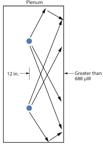
Reflectance: The next consideration is reflectance, or the amount of UV-C energy that bounces off the top, bottom and the sides of a plenum (Figure 4), toward the coil. Even though the minimum output level is met, reflectance has not yet been added in. If the plenum is constructed of galvanized steel, at least 50 percent of the UV-C energy striking its surface would be reflected as a single bounce value, although as many as seven bounces are found in the view factor model.
Using a single bounce, though, provides a minimum additional (172 x 0.50) = 86 µW/cm2 that can be added to the 172 number for a total of (172 + 86) 258 µW/cm2, well above ASHRAE recommendations. Other surfaces, such as stainless steel, provide up to 40% reflectance and aluminum up to 75%. Providing additional reflectance not only increases the amount of energy striking the coil surface, it also provides more energy to kill microorganisms in the airstream. As air circulates through the irradiation field, “each pass” provides a reduction (in viability) per unit volume of microbes in the space[ii].
Calculating UV-C watts per square foot of coil surface
 Lamp manufacturers represented on ASHRAE’s UV committee agree that lamps might differ slightly in quality but not more than 5 percent in function. So now that ASHRAE’s recommendations have been met here, the acquired data can further simplify future designs.
It was found that an 80 Watt, 36-inch HO lamp worked successfully on a coil that was 1 meter square, or 10.76 square feet of surface area. If the lamp wattage is divided by the square footage of the coil surface (80/10.76) = 7.43, it’s seen that about 7.5 lamp watts per square foot of coil surface area will meet the recommendations. This then provides a simplified way to properly size future UV installs for most any coil, large or small.
As an example, a custom air handler might have a coil 85 inches in height and 120 inches in width. This equates to a coil surface area of 70.8 square feet (about 35,000 cfm) and if that is multiplied by the aforementioned rate of 7.43 (70.8 x 7.43), it totals 526 Watts.
Unlike our one meter square coil example above, size wise, this coil would be more efficiently and affordably covered by four 61-inch HO (360°) lamps that are 145 Watts each (4 x 145) = 580, or 580 Watts total. This works well, and the slight overage will add to a higher fly-by kill ratio of infectious microorganisms.
UV-C retrofits can be a low as $0.15/cfm
UV-C retrofits are relatively simple to perform and the cost for a properly designed system of 10,000 cfm or more can be as low as $0.15 per cfm or, often less expensive than a properly performed coil cleaning procedure.
For larger installations that require multiple lamp rows, the overlap of light energy that is created helps to benefit the design, i.e. light from lower rows reach the top of the plenum and the overlap from upper rows reach the bottom of the plenum (Figure 4). This also benefits the sides of the plenum and makes yet another contribution to the kill ratio of infectious microorganisms in the air.
Also worth noting, all parts of the plenum downstream of a cooling coil are subject to the accumulation of contaminants as well as the formation of condensate; this is the perfect recipe for microbial growth. Using UV fixturing that provides a 360° irradiation profile allows most of the surfaces of the plenum to see UV-C energy, both directly and through better overall reflectivity. This keeps the whole plenum clean and reduces the potential for unmanaged microbial carryover to the occupied space—and has been shown to further reduce maintenance.
The exercise of distilling complicated information to its simplest form enables engineers to write more meaningful specifications and allows users to easily convert standard lamp Watt labeling to the more easily utilized lamp Watts per square foot of coil surface. In addition, it is always advisable to use non-proprietary components with agency approvals, long warranties and local sources of replacement materials.
Retrofits to UV-C products are reasonably simple and justifiably affordable. And as long as they are maintained, UV lamp systems most always have the promise of short paybacks, reductions in maintenance and employee absenteeism and the sustainability of heat transfer—for minimal energy use, longer equipment life and less downtime.
Sidebar
ASHRAE’s UV-C committee, TC 2.9, has published technical guidance on UV-C systems in the 2008, 2011, 2012, 2015 and 2016 Handbooks. Chapter 60.8 of the 2015 Handbook, HVAC Applications discusses coil surface irradiation. In this Chapter the TC 2.9 Committee established minimum irradiation levels for cooling coils specifically to:
- Eliminate mold and bacteria
- Reduce and/or eliminate coil cleaning, and,
- Sustain coil performance—with specific emphasis on potential energy savings in existing systems.


Join the conversation: